Microforge is a sparkled name in the biotechnology world, where the use of micropipettes is always on the tremendous hype. But to know how to use microforge is inevitable in this regard. It is an instrument used in glass equipment production, especially micropipette while seeing the tip with a built-in microscope. The microforge enables forging various sorts of pipettes via passing multiple incredible steps that come under the micro-works. If you want to understand how to use microforge, you have to stick with this guide till the end.
Related Products on Amazon
What is and How to use Microforge?
Before unveiling the actual facts regarding how to use microforge, it’s quite important to know why and where this instrument is used for. Microforge is a versatile tool to fashion pipettes for in vitro usage, as per your own preferences.
If you’re into learning more niche tools and techniques, check out our deep dives like how big is a French curve
See Major Types of Microforge
To learn how to use Microforge, know what are major types of it. Generally, microforge is of two distinct types: Analog & Digital. There are symmetric and instrumental variations with uses distinct them apart. Otherwise, the output – Pipette Production is the same in both cases. Now let’s see what makes both of them different from each other and the outputs that come across them.
1. Analog Microforge
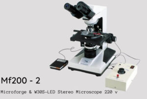
When it comes to Analog Microforge, different variants come across it. But among all, MF200 is assumed as one of the highly flexible microforges specially designed to fashion glass micropipettes and other related tools. It is a simpler, more durable, and more reliable device than others. By the way, it can be used for many purposes, like;
- Pipette polishing
- Pipette size-reduction
- Contact stretching to sharpen largely bore pipettes
- Carbon fibre electrode sealing
- Various pipette configuration production
Due to the many applications of this instrument, one must ponder how to use microforge, especially the Analog type. So, here are some core features that deliberately emphasize its significance.
- Microscope deployment in order to manipulate the pipettes
- Distinct model of the filament holder that allows heating element attaching directly to the microscope objective
If you see the variants of the Analog Microforge, you will really wonder what a number of distinct types are here, which entails MF5, MFG-5, MFG-5A, MF200, MF-900, MF-830, etc.
2. Digital Microforge
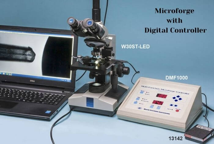
How to use microforge is a question that’s vigorously sorted by a digital controlling microforge too. By the way, different names are across the line regarding Digital Mocroforge. But DMF1000 has more hype than the rest of the others. DMF1000 is a Digital Microforge controlled by a microprocessor. It not only fabricates small patch-clamp glass pipettes; rather, it can contrive larger injection pipettes too. By the way, besides fabricating the pipettes, this microforge is mainly used for;
- Microforging holding pipettes
- Microforging bevelled injection pipettes
- Polishing patch-clamp pipettes
- Calibrating pipette tips for microinjection
How to use Microforge
Microforge, either Analog or Digital, each has a specific methodology to use. Both instruments have their own value with their specific ways of applications. Apart from their applications, the instrumental variation forces one to figure out how to use microforge either one way or another. Let’s see them one by one.
How to use Microforge Analog

The use of Analog Microforge somewhat seems more complicated than the digital one due to having more operating steps involved in it. Among various complicated versions of it, here I’m going to elaborate on the most versatile piece of microforge – MF200 microforge. Just follow the given steps and learn how to use microforge in terms of analog.
Components – that are used in operating the system
The complete MF200-1 (110V) and MF200-2 (220V) systems include both the microforge and matched microscope; i.e., MF200-M1 (110V) and MF200-M2 (220V) include the Microforge only. Within these instruments, the following components are provided to function well.
i). Optics
- Among all the commercial microforge, the MF200 is the only one that entails a 40X long-working distance (LWD) objective. Due to its enough magnification power, pipettes can easily be polished as small as half a micron – 0.5mm in diameter.
- In order to measure the dimensions of the pipette tip, a linear eyepiece reticle and an optional angular reticle are available within the system.
- Apart from these, there are also some other optional accessories in order to augment the system’s functionality. It entails a 25X LWD objective for the W30S microscope, etc.
ii). Heating Filaments
In the MF200 microforge, H2, H3, and H4 are functionally distinct heating filaments in order to have diversifying applications. The key design features of these heating filaments are the filaments’ low heat capacity and low thermal expansion.
- Low Heat Capacity
- It allows reaching fire-polishing temperatures without excessive heat. It also permits the pipette tip to be brought close to the filament during polishing without fear of collapsing the pipette tip and eliminates the need for an auxiliary air cooling system.
- Low Thermal Expansion
- It ensures minimal displacement of the filament during heating. This feature takes much of the guesswork out of tip placement in relation to the filament.
iii). Microscope
When you move to learn how to use microforge, learning about microscopes is inevitable. The microscope has been conformed with WPI research-grade microscope model W30S to provide an uncomplicated and complete system with unusual and remarkable functionality. The Filament Adjustment Assembly supplied with the microforge has been designed to fit both the 40X LWD objective with the optional 25X LWD objective for the W30S microscope.
iv). Power Controller (Control Unit)
- The MF200 is powered by a 12VDC adapter to supply power to the Control Unit. Being electrically stable and reproducible, this is more firm and profound. The positive sign is that any fluctuation in the main voltage input will not affect the output to the filament. Thus, it leads to the same polishing results in the same settings over time.
- A push-button polish switch on the Control Unit turns the heating filaments On and Off.
- An optional footswitch is also provided for complex fire polishing. The optional footswitch leaves the hands free to move the pipette and control the variable heat adjustment on the Control Unit.
Operating Instructions of the Microforge
In the context of how to use microforge, it is so crucial to determine its operation modules. Different steps are involved here to analyze the operating instructions of the microforge. It includes;
Setting
There are four steps involved in the setting of the microforge;
- Mount the LWD to the microscope
- Mount the Filament Adjustment Assembly to the microscope
- Position the micropipette holder on the microscope stage
- Install the heating filament
Basic Operations to learn how to use Microforge
- Turn on the power to the microscope and choose the desired filament.
- Mount and connect the heating filament. After that, bring the filament into focus without using the microscope, and adjust its position by moving it in or out and from side to side until the filament wire is centred approximately 3mm below the objective.
- Move the filament in the filament clamp until its shadow appears to look via the microscope. Some vertical adjustment may also be required to bring the shadow into the field. Because it brings the filament into a clearer view. With the Horizontal Adjustment, position the end loop of the filament to the far right side of the visual field.
- Power up the MF200 unit. For this, it has to connect the AC/DC converter to the power input jack on the Microforge Control Unit and the wall socket. A light in the POWER switch indicates that the unit is powered up.
- Position the heating filament and the pipette. With the Power-on setting, diminish the Polish button several times at various heat settings in order to see the filament loop expansion and figure out the actual position of the pipette with its relation.
- Adjust the pipette in the pipette holder that is horizontally positioned on the microscope stage. Thus, the pipette tip will slightly pass the centre of the objective.
- Calibrate the Filament Power Select switch and Heat dial. These are enough operational instructions of a basic level that tell you how to use microforge.
Applications of Microforge
In order to determine how to use microforge, it’s quite important to know what applications are required in this regard.

- Breaking
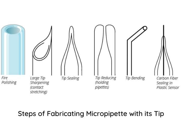
First of all, the pipette tip has to break down. It can alter the pipette tip opening to expand the diameter. For this, it can be used either a useless pulled pipette tip or install a fine tip pipette to the vertical pipette clamp.
- Polishing
The polished pipette tip is best for use to get a firm cell holding or patch clamping. Install an open pipette tip to the pipette holder clamp vertically to polish the tip. Let the tip move close to the heater slowly in a back and forth movement until the tip is polished. Once the polishing is done, inspect and measure the polished tip using higher magnification objectives.
- Sharpening & Tipping
A sharpened tip of a pipette leads to the target due to having a bigger opening. For this, install a fine tip pipette to the vertical pipette clamp. Turn on the heater with a higher heat level and move the tip over it by touching the heating coil with the glass tip side. Move out the pipette tip from the heating coil rapidly as a sharp tip is produced.
- Bending
In some cases, bending also becomes important as polishing and sharpening the pipette tip, i.e., an embryo holding pipette. And for this, install a longer tip pipette to the horizontally aligned pipette clamp. Turn on the heater with a high heat level and move the tip over the heater coil to bend the tip. When the tip is bent, take proper control over closing the heat wire and move out from the heat coil steadily.
All of these are the basic to advanced level instructions regarding how to use microforge with the mean of analog type – MF200. These are quite enough to fabricate a micropipette with its fine tip.
How to use Microforge Digital

DMF1000 is usually more in use among the latest names in digital microforges. But how to configure it is crucial to know. So, let’s learn how to use microforge by digital means. Just navigate the instructions.
Display Menu
- First of all, power up the DMF1000 unit and connect the cord to the power input jack.
- Turn on the power switch and plug the filament pins into the controlled panel. Then plug the filaments into the sockets.
- Once this microforge unit is started, the setting options display over the screen in order to set as per the requirement.
- To signify the power up the unit, the Heat and Timer displays illuminate.
- As the unit is turned on, both the readouts display 000.
- At the moment,
- The TIME selection is set to Auto.
- The MODE selection is Heat.
- The Air On light is Off, and
- The Heat On light is off.
How to use microforge with Mounting with Microscope
How could it be possible to determine how to use microforge without a microscope? Thus, to run the system of a microforge unit, a built-in microscope is set along with it, on which it the filament is mounted and observes the fashioning modes of glass equipment or micropipettes.
- In order to set the Microforge unit in Manual Mode, press the “TIME” button at first. The press “RUN” button sends the current via filament, and the “Heat On” lamp will be turned on.
- Press the Increase & Decrease buttons from setting 0-99.9% and set the Heat readout, varying the amount of power applied to the filament. Generally, 30% is recommended to initiate.
Note: Avoid starting the high readouts and start with the low end. If needed, increase gradually with a little bit. Because higher heat may shorten the filament’s lifespan and the overheating pipette tip.
- Now to see the expansion of the filament loop, press and hold the RUN button more than once with varying heat settings. Thus, you can figure out the positions of the pipette correlate with the settings. More heat will result in more expansion in the filament.
Set the Time
- The time has to be set via arrow keys to move the decimal point, among other settings.
- For this, Right Arrow on the screen will set the time approx 6 minutes. Whereas Left Arrow on the screen will set the time for approx 9.99 seconds before back to 0 and starting again. When the decimal is at the second position means 00.0, and the max time is 99.9 sec of the counter before moving back to 0 and starting again.
- After fixing the time, hit the TIME button that will change the time and heat settings from Auto to the Set and Desired mode as per your own need.
- Now checking the settings with a micropipette is crucial to determine whether the setting is set or not. So, hit the RUN button, and the time will decrease to 0.
- These settings can be saved by pressing the STORE button for further use. Just use the arrow keys to choose the location and press the MEM button to store it.
By following all of these instructions, there will be nothing left in the context of how to use microforge if one has to move with digital type – DMF1000.
Final Words
In order to fabricate glass instruments, the significance of microforge is inevitable. But it will not be beneficial for you until you don’t learn how to use microforge. Analog and Digital are two major and most magnificent kinds of microforge. This guide is overwhelmed with the incredible ways of using microforge, especially in manufacturing micropipettes via both types of microforge. Once it has learned how to use microforge, that will be no less than a remarkable breakthrough in scientific research. So, make sure to go through the whole article and get amazing facts about this useful instrument.


